Product overview
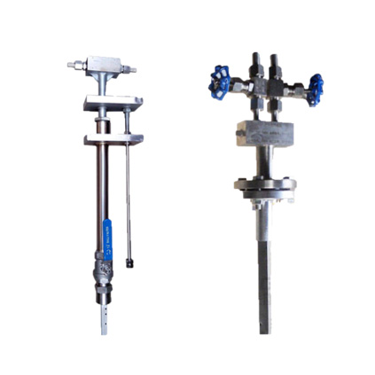
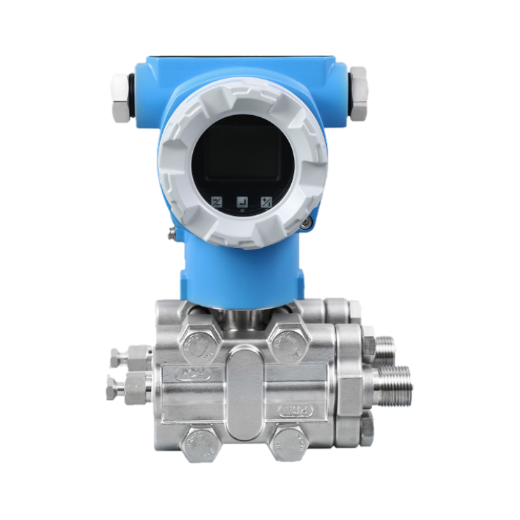
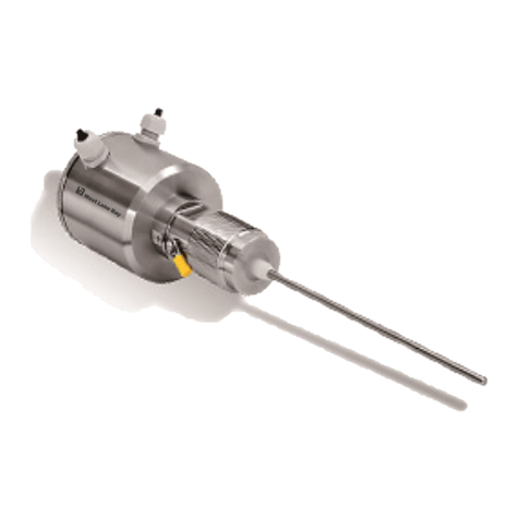
The FBG velocity-averaging tube flowmeter is a high-precision measuring instrument developed according to advanced aerodynamic principle supplemented by the wind tunnel test on the basis of pitot tube speed measuring principle. It's a differential pressure type and rate average flow sensor. The difference between the average total and static pressure in the fluid through the sensor is used to indicate the flow. It's often used to measure the flow of liquid, gas and vapor.

Product features
● There is no movable part structurally, and the sensor lifetime and long-term stability can be ensured;
● High accuracy (±0.5~1.0%F.S) and good repeatability (±1.0%);
● The flowmeter is of small pressure loss, greatly lowering the energy consumption;
● After the static pressure inlet of the flowmeter is taken on both sides of the sensor, the flowmeter is extremely insensitive to foreign matter and dirt in the medium;
● The flowmeter is basically maintenance-free with simpel installation and low expense;
● To facilitate the use by the user, our company's VERIS flowmeter is of integrated and split structure;
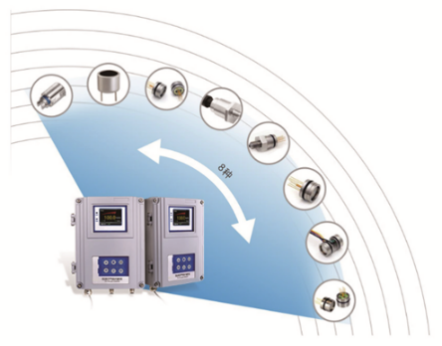
● The intelligent integrated VERIS flowmeter is of advanced circuit design with strong function, micro-power consumption, display of flow information on the large LCD screen and internal memory unit ensuring the safety security;
● As for the integrated VERIS flowmeter system, the battery power supply and external 24VDC power supply can be used with output 4~20mA pulse signal and Hart protocol;
● As for the measurement molded surface designed according to aerodynamic principle, the fluid traction and vortex street peeling force produced can be very small by the special fabrication processing;
● The static pressure hole on the side is taken, and the static pressure generated is in front of the point of separation between the fluid and the sensor and a stable non-pulsating differential pressure signal.
Technical parameters
Applicable pipe diameter |
|
Measurement accuracy |
|
Repeat accuracy | ±1.0% |
Applicable temperature | -100-500℃, reaching to 800℃ under the special situation |
Applicable pressure: | 0~25MPa, reaching to 40MPa under the special situation |
Upper limit of measurement | Determination as per process requirement and probe strength |
Lower limit of measurement | Depending on the minimum differential pressure requirement of measurement |
Gas, minimum differential pressure: 0.025KPa, and flow velocity: 4.5m/s | |
Liquid, minimum differential pressure: 0.260KPa, flow velocity: 0.6m/s | |
Steam, minimum differential pressure: 0.400KPa and flow velocity: 9.7m/s | |
Range ratio | Range ratio-10:1 in the premise of ensuring precision |
Applicable medium | Full package, unidirectional gas, vapor and liquid with a viscosity not greater than 10cm |
Straight pipe section | Front 7D and rear 3D generally |
* Equipment differential pressure transmitter, and intelligent flowmeter calculator condenser; Integral welding or flange or thread.
Product model selection
FBG-V | VERIS flowmeter | |||||||||
FBG-A | Flute velocity-averaging tube flowmeter | |||||||||
Nominal diameter | *** | 100 indicates DN100 | ||||||||
Structure form | Z | Intelligent integration | ||||||||
L | Split type | |||||||||
Measuring medium | W | Liquid | ||||||||
L | Gas | |||||||||
B | Steam | |||||||||
Body form | 1 | Pipe flange type | ||||||||
2 | Flange connection plug-in type | |||||||||
3 | Threaded connection plug-in type | |||||||||
Pipe static pressure | A | 0~0.6MPa | ||||||||
B | 0-1.0MPa | |||||||||
C | 0-1.6MPa | |||||||||
D | 0~2.5MPa | |||||||||
E | 0-4.0MPa | |||||||||
F | 0~6.3MPa | |||||||||
G | 0~10MPa | |||||||||
H | 0~16MPa | |||||||||
1 | 0~25MPa | |||||||||
J | 0~40MPa | |||||||||
Technological conditions | 0 | Ordinary | ||||||||
1 | Corrosion prevention | |||||||||
2 | High temperature | |||||||||
3 | Explosion proofing | |||||||||
Compensation method | 0 | No compensation | ||||||||
P | Single pressure compensation | |||||||||
T | Single temperature compensation | |||||||||
0 | Full compensation for pressure and temperature | |||||||||
Integrated signal output | 0 | Without | ||||||||
1 | 4-20mA | |||||||||
2 | Pulse | |||||||||
3 | Hart | |||||||||
Integrated power supply mode | K | Internal battery power supply | ||||||||
L | Battery and 24VDC double selection power supply | |||||||||
M | External 24VDC power supply | |||||||||
* It's necessary to provide pipeline inner/outer diameter and pipeline material;


 QQ客服
QQ客服
